mACT : Work Environment
The mACT Work Environment has numerous benefits over the standard environment as it structures the interface more logically – specifically it organises ARCHICAD to:
- Set the preferences for optimal performance & data safety
- To include essential menus & toolbars on your screen
- Expand & rationalise the list of Shortcuts
Work Environments are saved locally on each computer and therefore need to be separately loaded on each individual workstation.
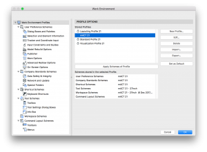
- ARCHICAD > Work Environment
- Ensure you are at the top of the tree called “Work Environment Profiles”
- Click “Import…” and “Browse” to the folder where you extracted the template. “Choose” the following folder /Extras/WE/
- Select “mACT 21” and “Import”
- Select “mACT 21” under the Stored Profiles, “Apply Schemes of Profile” and “Set as Default”
- “OK”
[asideguide type=”tip”]We invite every user to customise this WE to suit their specific requirements. Make sure you save these custom schemes with, for example, your initials appended. This way, if somebody else needs to use your computer, they can always switch back to the base mACT WE.[/asideguide]
mACT Toolbar
The mACT Work Environment comes with the mACT Toolbar, which makes commands hidden in the default ArchiCAD menu structure more directly accessible:
![]()
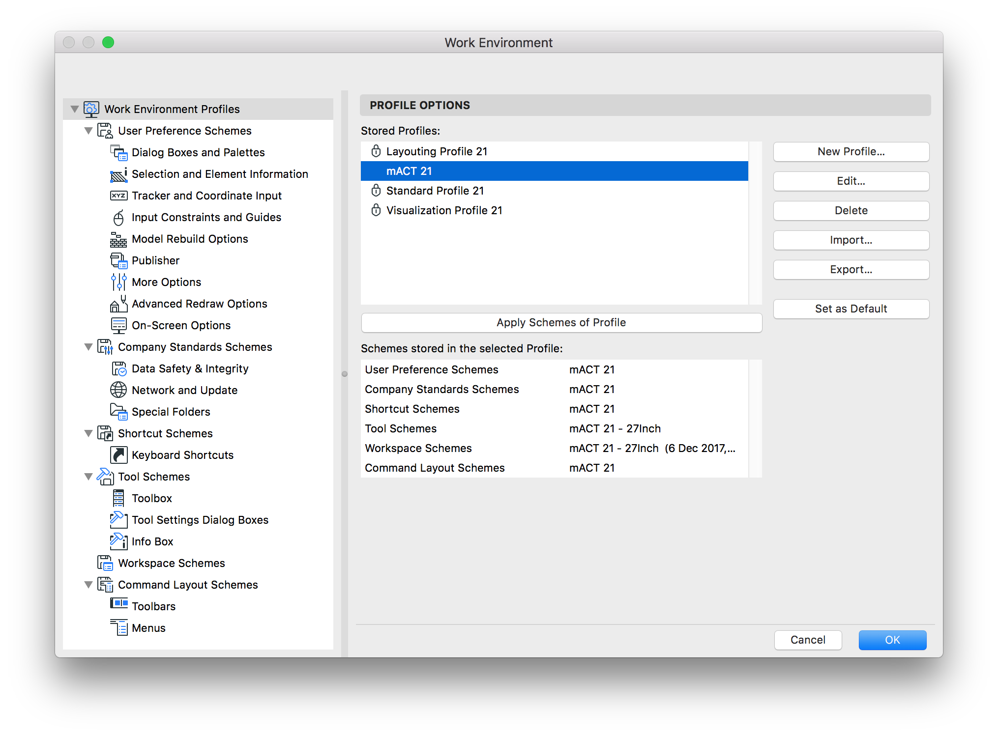
Shortcuts
The mACT Work Environment provides a lengthy list of custom keyboard shortcuts, expanding on the default Shortcut Scheme to facilitate access to regularly used functions.
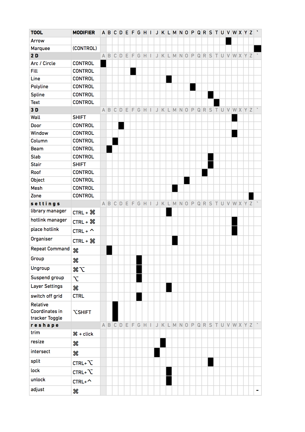
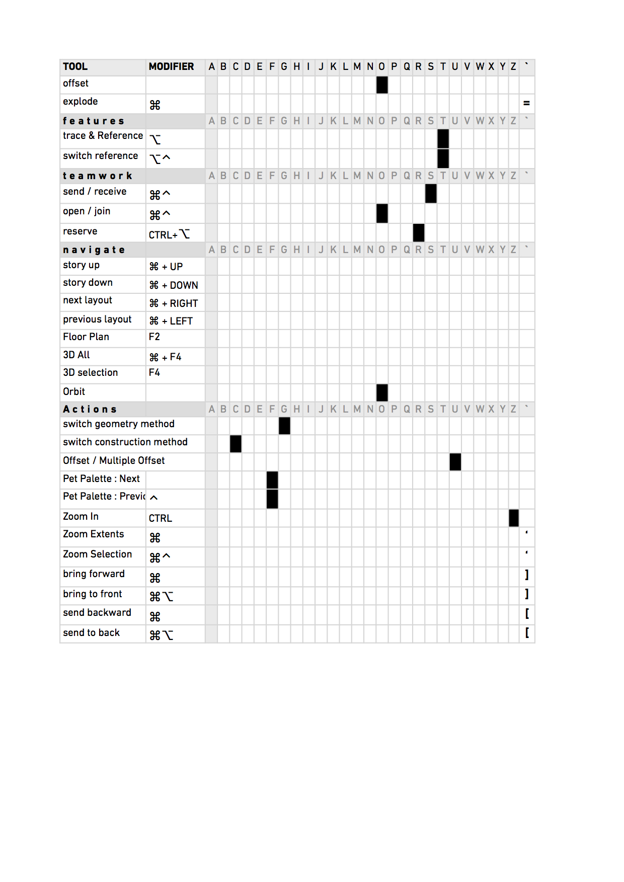
At any time you can get a list of all shortcuts in your browser via…
ARCHICAD > Work Environment > Shortcut Schemes > Keyboard Shortcuts > Show in Browser

Please note that OS X has a default keyboard shortcut that enables / disables the hiding of the dock. Best to disable this shortcut via System Preferences > Keyboard > Shortcuts > Launchpad & Dock > un-tick “Turn Dock Hiding On/Off”.

mACT : Libraries
The mACT Library includes a multitude of custom Library parts, a detailed library inventory is available here.
CADSWIFT Library & Demo versions
mACT also includes the free CADSWIFT Library as well as demo versions of the Infinite Tools. We have contributed to their development, thus we highly recommend you evaluate these tools as they are currently the only way to achieve certain drawing types, e.g. automated window schedules of full window assemblies.
mACT : Attributes
Attributes
mACT includes a comprehensive set of Attributes which should provide for the majority of users to work with the template without further customisation. However, mACT is a framework for ARCHICAD which whilst providing a robust starting point also acts as a guide to permit users to quickly extend the template to suit the particular requirements of their office or project.
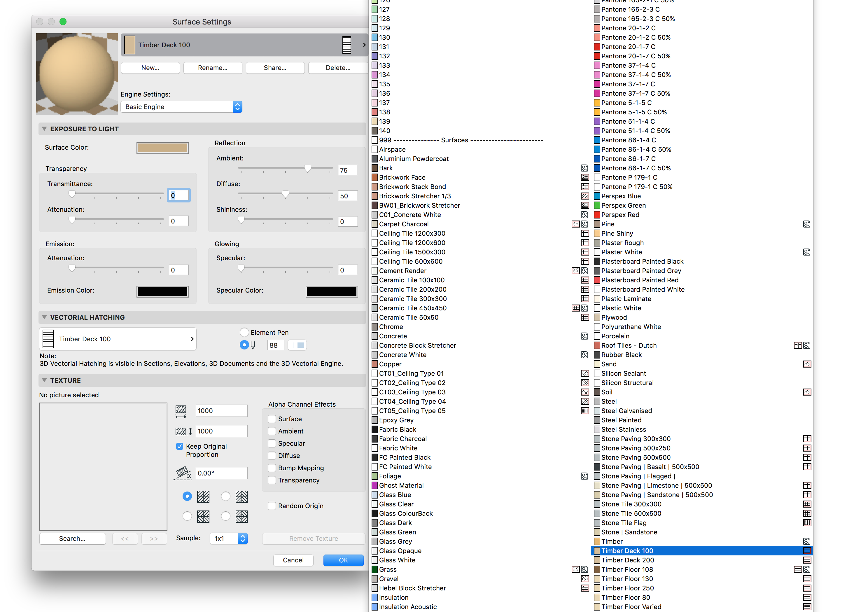
Whilst we think the attributes provided fit the needs of most users, we understand everyone has their own graphical preferences and so may wish to modify the attributes we have provided. There is no issue with doing this, but please keep in mind that the attributes provided are used throughout the template – both assigned to default Tool settings and Favourites, and used in other Attribute definitions (e.g Timber Deck 100 fill is assigned as Vectorial Hatching for Timber Deck 100 material). Hence be very careful when modifying existing Attributes as this can impact many elements and locations in the file.
[asideguide type=”alert”]The best approach to creating new Attributes is to duplicate an existing one and then modify that duplicate to create the desired outcome.[/asideguide]
It is important that Attributes and their Index Numbers (hidden to the user except via the Attribute Manager) are consistent across all ARCHICAD files on a Project, to ensure consistent display of element properties and facilitate their transfer between files. Attributes, need to be carefully and actively managed by the most experienced ARCHICAD User on a Project or in the Office for each project.
Layers & Layer Combinations
Layers
Layers are the primary means of organising or classifying Model Elements in ARCHICAD and controlling their visibility in various Views.
Layers in mACT are structured around classifying elements according to the Australian NATSPEC Specification System.
Although a Building Element classification system such as Uniformat (US) or Uniclass (UK) may be be more suited to categorisation of layers, Australia has currently no recognised system thus the NatSpec Worksection system has been selected as the most suitable locally accepted system for this purpose.
The mACT layer system follows the basic workflow of first building a digital Model of the building and then annotating and generating documentation from the same model. Layers are organised around the following groups of elements:
| 0 > PRESENTATION & DRAFTING | Presentation elements – (2D + 3D) People, Vehicles, diagram elements, etc |
| 1 > REFERENCE & ANNOTATION | Annotation elements – this is where all annotation (typically 2D) of the Model is placed including Labels, Drawing Markers, Dimensions, Room Labels, etc The REF layers are for the various Markers such as elevation, section or detail markers. |
| 2 > SITE & LANDSCAPING to 9 > ELECTRICAL |
The Model – these layer groups are where your building elements are placed (in 3D!). |
| MOD, REF, SEO | Non-building or file structure elements – Hotlink Master layers, construction guides, consultant drawings, solid element operation elements, etc |
Generally, the organisation of layers is hierarchical, the layer names are alphanumeric and layer names use easy to remember abbreviations without spaces in the singular (no plural terms).
There is a basic principle of modelling in 3D in ARCHICAD, however where 2D elements are required these reside on the same layer as a normal 3D element would. For example a 2D dashed line representing the alignment of a concrete wall hidden behind an element would be placed on the 03 WallIntConc layer along with a visible 3D wall element.
Layers are assumed to be scale agnostic unless otherwise indicated in their layer naming – scale specific layers generally only occur in the annotation layer groups as building elements are never scale specific.
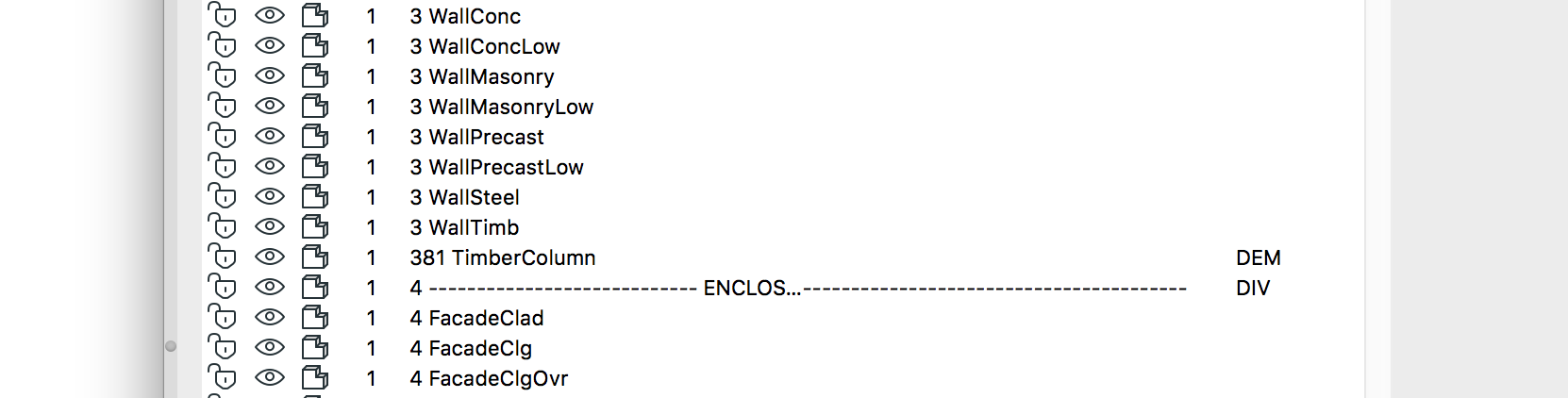
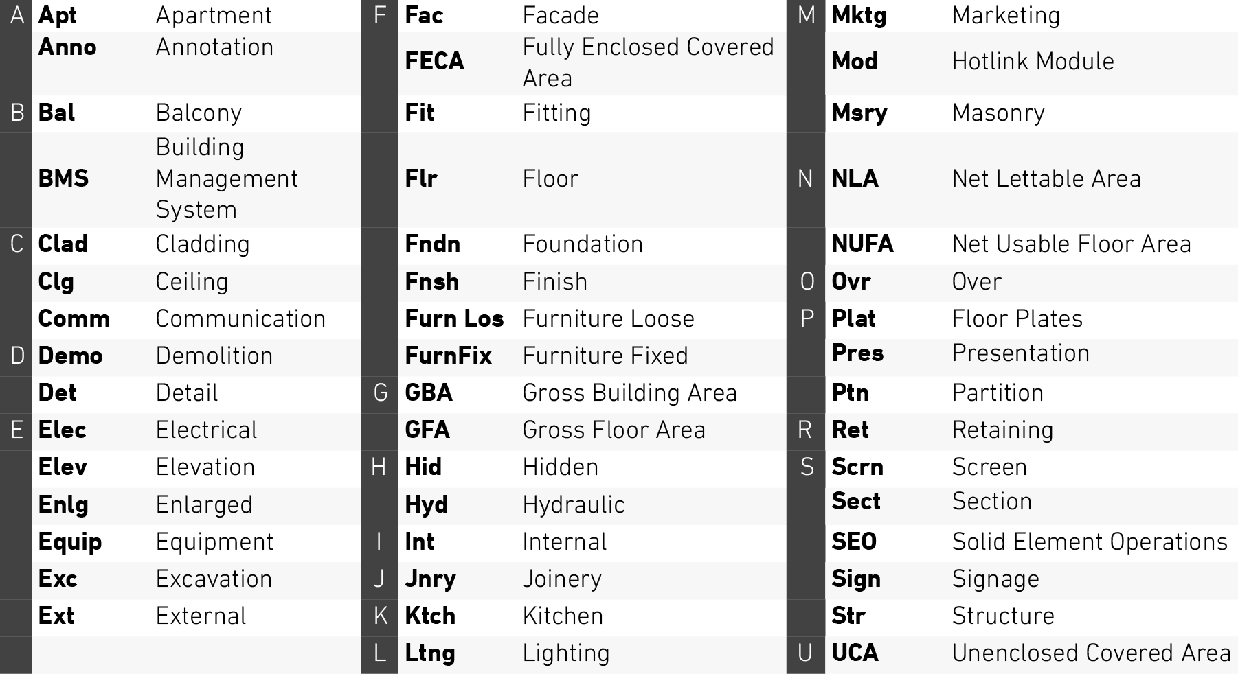
Layer Abbreviations
To be able to read the layer name in the info box it needs to stay under a certain length. This necessitates the use of Layer abbreviations:
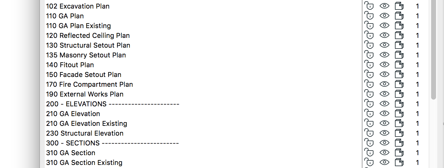
Layer Combinations
mACT contains a comprehensive list of Layer Combinations to allow for flexibility in appearance of various View Sets. Combinations are generally numbered according to the View type they are assigned to, which are in turn numbered according to the drawing set the corresponding Views are part of in the Layout Book – please refer to the Document Numbering System (DNS) section below for more information on this topic.
Note that hidden layers are also LOCKED, allowing them to be not displayed on popup palettes throughout ARCHICAD.
Pens & Pen Sets
Pen Sets in ARCHICAD control the colour & weight of all available pens used to draw elements. Since ARCHICAD 10 it has been possible to create multiple Pen Sets, enabling the user to quickly change the appearance of elements (colour and line weight) by simply applying a different Pen Set to a view.
There are two basic approaches to using the Pen Table in ARCHICAD.
The first is to assign pens using the same principle as conventional drafting where there are around 7 pens (but can be more) with increasing weight (a la Rapidograph pens) – this approach is commonly know as a Pen-by-Weight system.
The second is to leverage the 255 pen depth of the Pen Table to assign certain pens to certain functions (e.g. Pen 4 for Structural Cut Lines) – commonly known as a Pen-by-Function system.
mACT uses a Pen-by-Function system whereby elements of certain categories are assigned specific pens which are not shared with elements of a different category.
Whilst this is slightly more complicated than a simple Pen-by-Weight approach using only a few pens, this allows for much greater control over the appearance of elements in various forms of documentation.
A few examples of functions this system enables are:
- Visual distinction between elements when modelling, e.g. all structural elements have red outlines;
- Adjustment of pen weights for various element types based on the drawing type, e.g. grey out everything but the concrete on concrete setout drawings, beef up pen weights in 1:5 details, etc;
- Adjustment of pen weight for elements whilst keeping annotation weights the same across scales, e.g you don’t usually want to fatten your leader lines at the same time as building elements which may be using the same pen – Pen-by-Function splits annotation pens from element pens;
- Generation of special Drawing types, e.g. Fire Compartment Plans – use dedicated background pens to change appearance of fire rated walls between regular and Fire Compartment drawings;
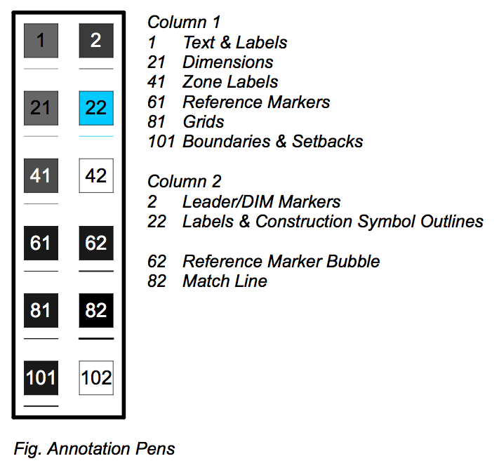
Pen Table
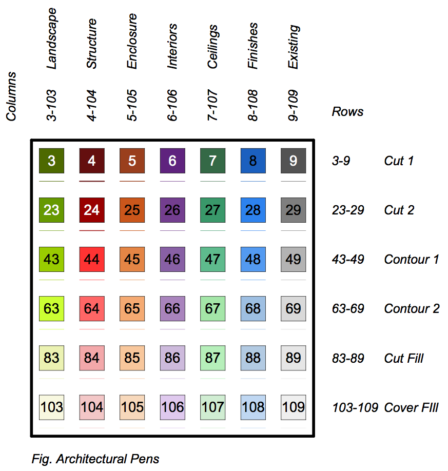
The mACT Pen Table can be subdivided into the following Pen function sections:
| Annotation Pens | Annotation Elements – Labels, Text, Markers, Gridlines, etc |
| Architectural Pens | Architectural Model Elements – Structure, Facades, Partitions, etc |
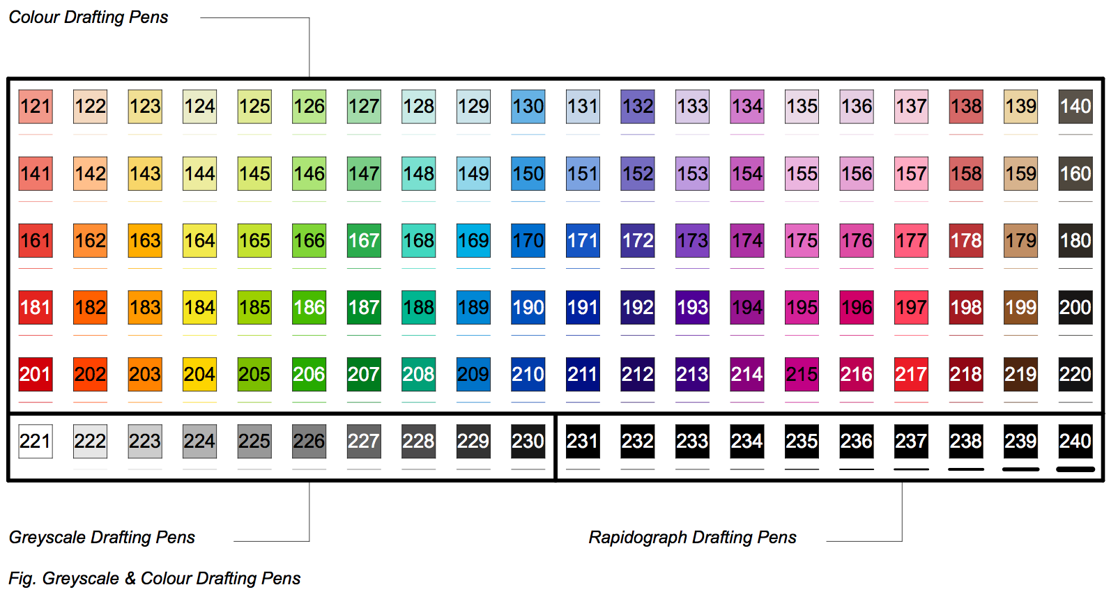
| Color Drafting Pens | Color 2D Sketch / Presentation Elements – People, Vehicles, Diagrams, etc |
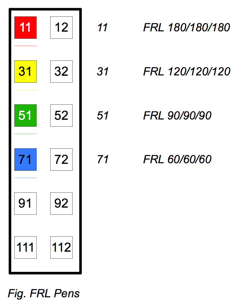
| FRL Pens | Fire Resistance Level – presets for FRL 60, 90, 120 and 180, additional pens reserved for additional FRLs |
| Markup Pens | … |
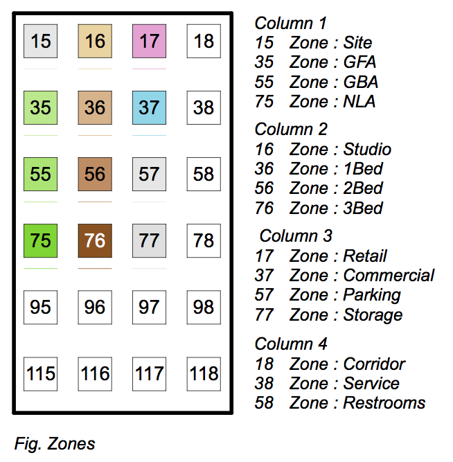
| Zones Pens | Zone colour pens – preset to change colours per Zone Category |
| Company Colours Pens | Company Colours – reserved for your specific branding |
| Greyscale Drafting Pens | Greyscale 2D Sketch / Presentation Elements – People, Vehicles, Diagrams, etc |
| Rapidograph Drafting Pens | Greyscale 2D Sketch / Presentation Elements – pen weights preset as per Rapidograph table |

Please note when you hover above a pen a detailed description of a pens typical usage appears.
Pen Sets
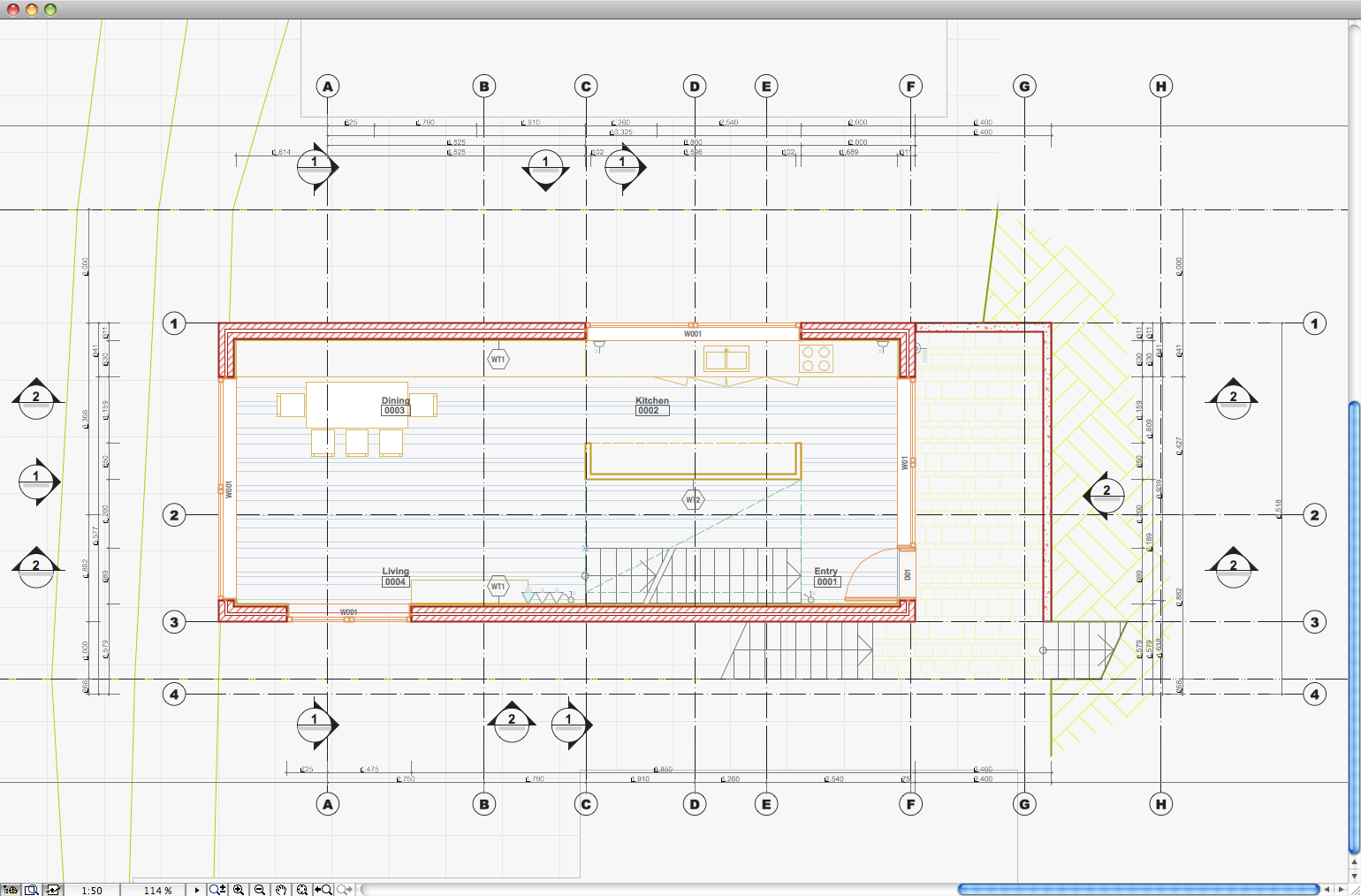
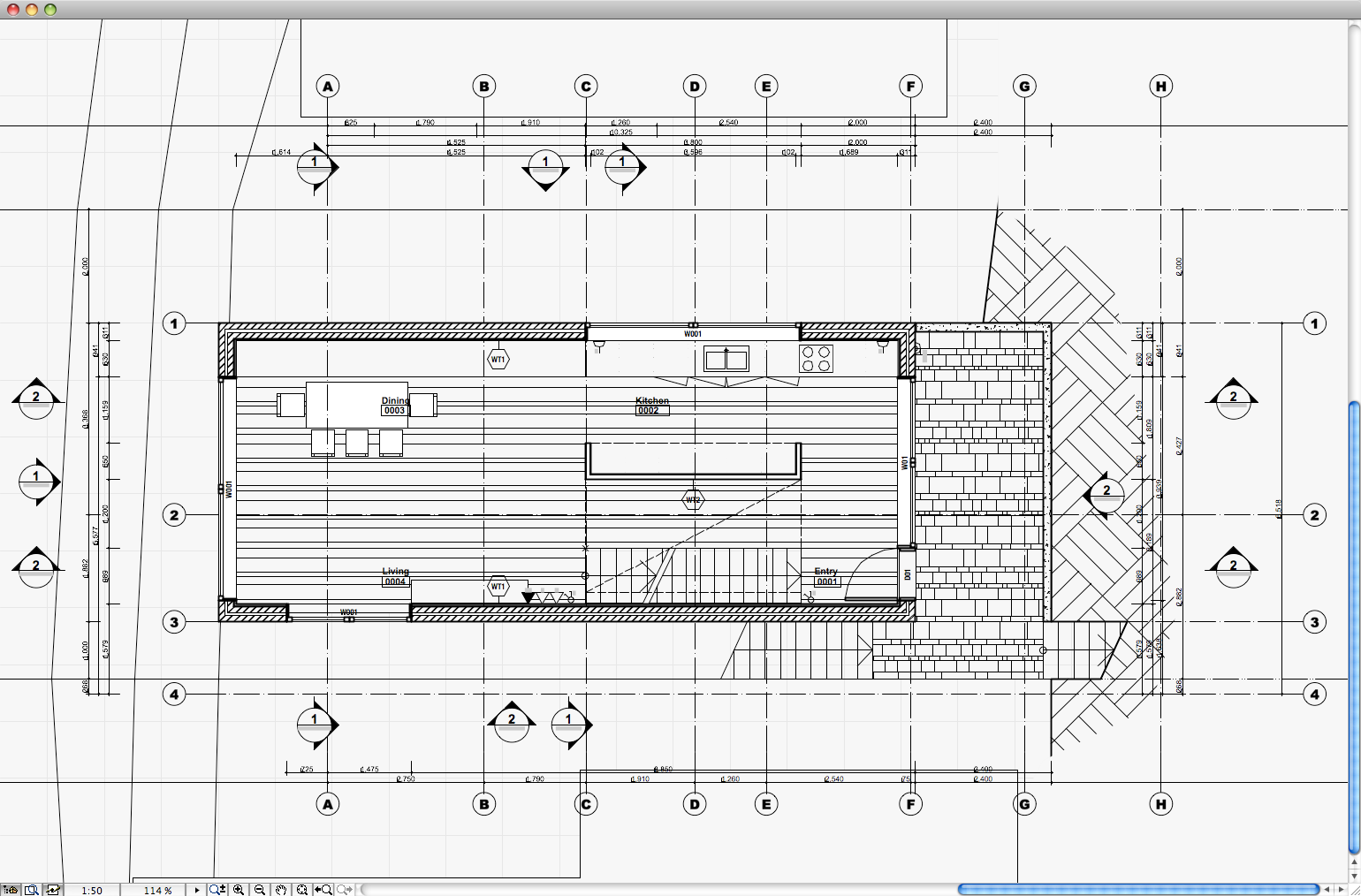
One of the key features of the mACT Pen Sets is the distinction between Pen Sets used for working – ‘Model’ Pen Sets – and Pen Sets for printing/publishing – the ‘Doc/Pres’ Pen Sets. The Model Pen Sets are applied to working Model Views as you edit the model or drawings and facilitate quick identification of elements via colour for various element types. The Doc/Pres Pen Sets (generally B&W or greyscale) are then applied to those Model Views when placed onto Layouts for printing.
The figures below illustrate the difference for the same plan.
Reference Pen Sets
Override external drawings’ pen sets with mACT Reference pen sets, which unifies their colouring and gives it a clear distinction from your ARCHICAD model.
Surfaces
mACT features an extensive list of Materials covering commonly used building materials and finishes.
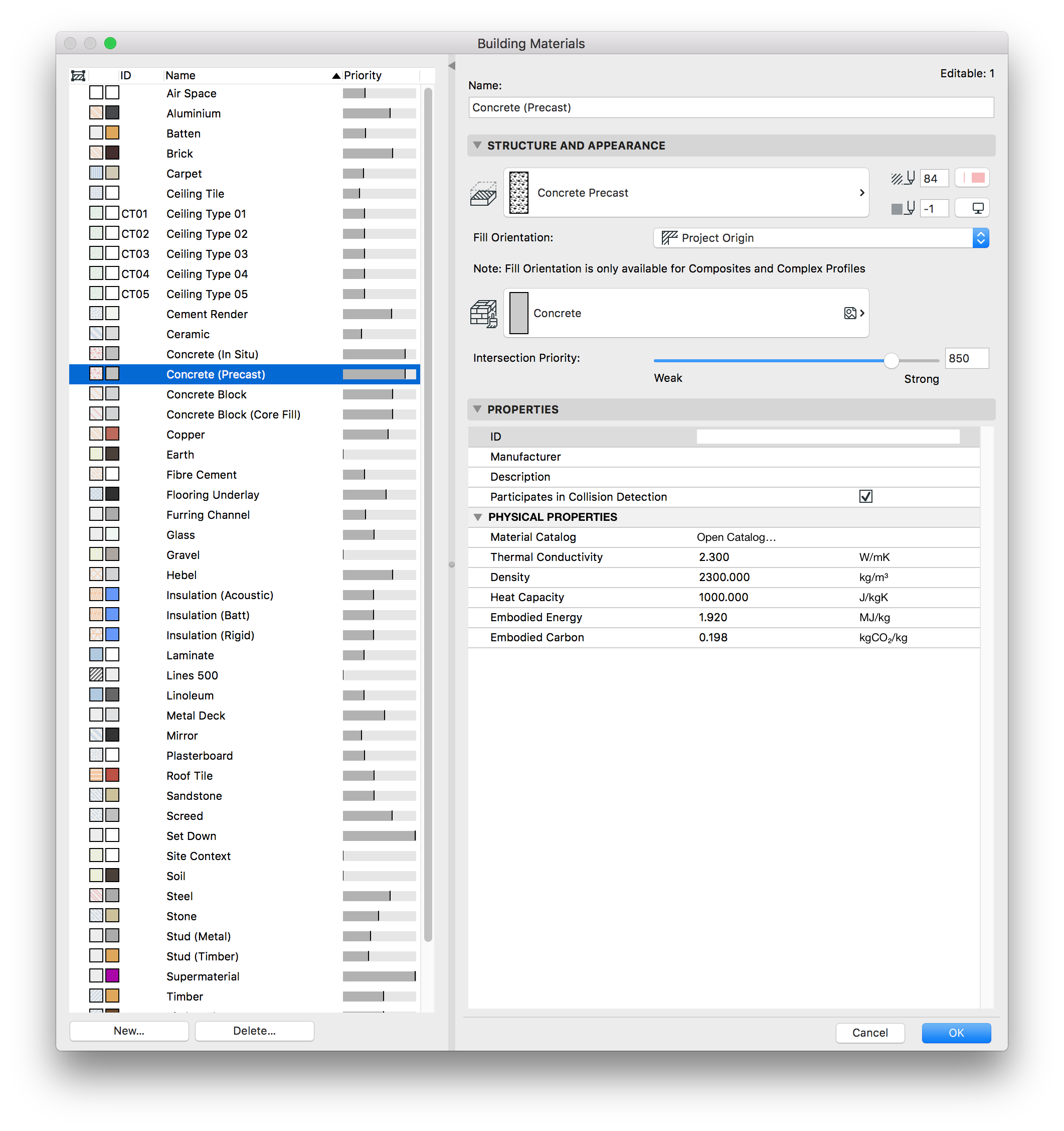
Building Materials
mACT 20 includes an extensive list of Building Materials, fully coordinated with Fills, Surfaces and Pen Sets.
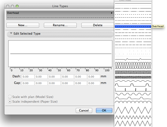
Line Types
mACT contains a set of Line Types grouped into three categories:
- Generic (e.g Dashed Short)
- Function-specific (e.g Overhead, Demolition)
- Element-specific (e.g Insulation Batt 100mm)
Fill Types
mACT features an extensive list of Fills covering commonly used building materials and finishes. As Fills can represent either the sectional (Cut Fill) or surface finish (Cover Fill) of building materials, there will often be the need for two fills to cover a particular material. In these instances the fill representing the surface finish is appended with an (E) code – e.g Cement Render can be represented by the fills Cement Render in section or Cement Render (E) in elevation.
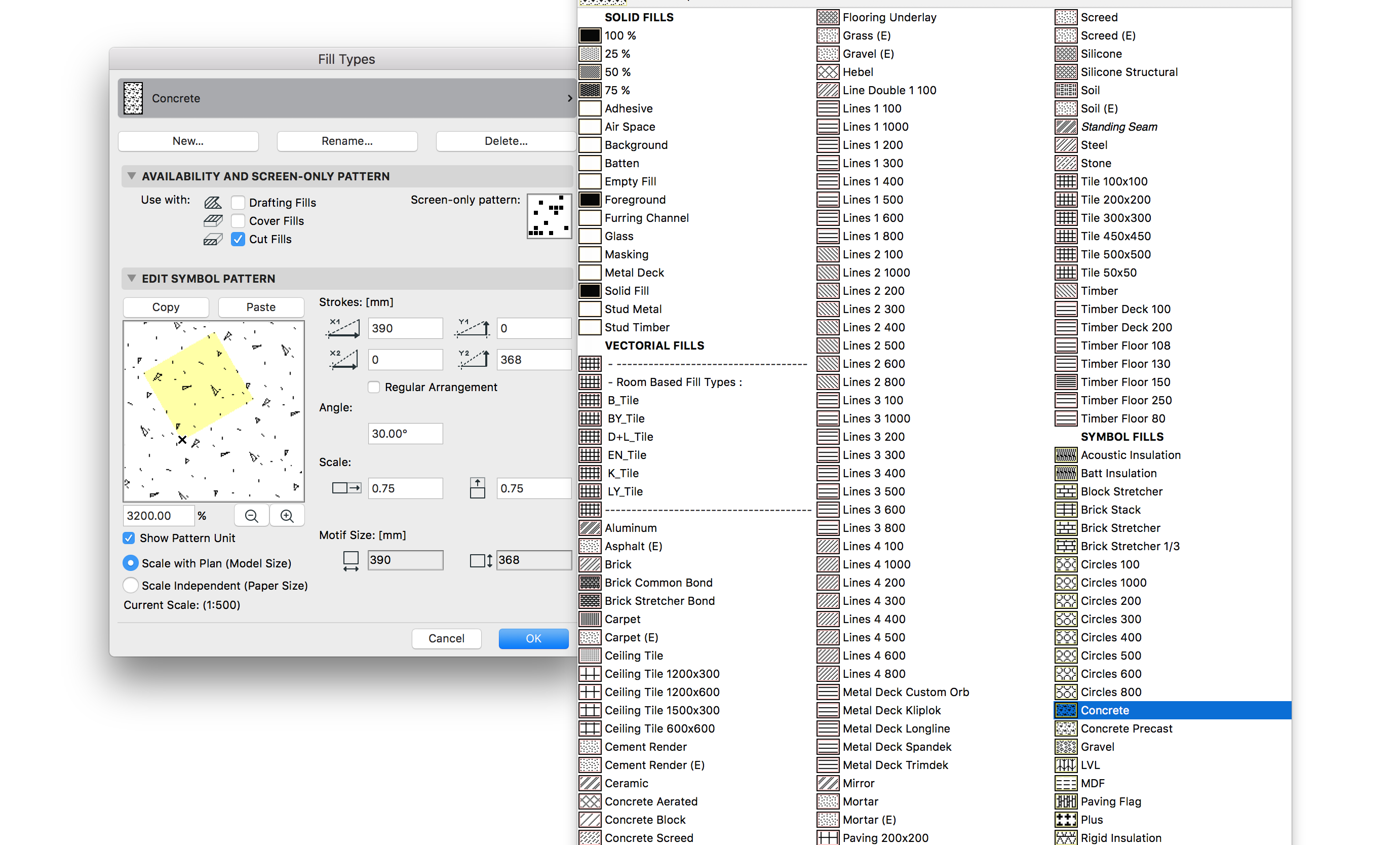
Also, mACT includes a number of Fills based on room types. This allows for quick global changes, e.g. if the Client or Builder changes tiles.
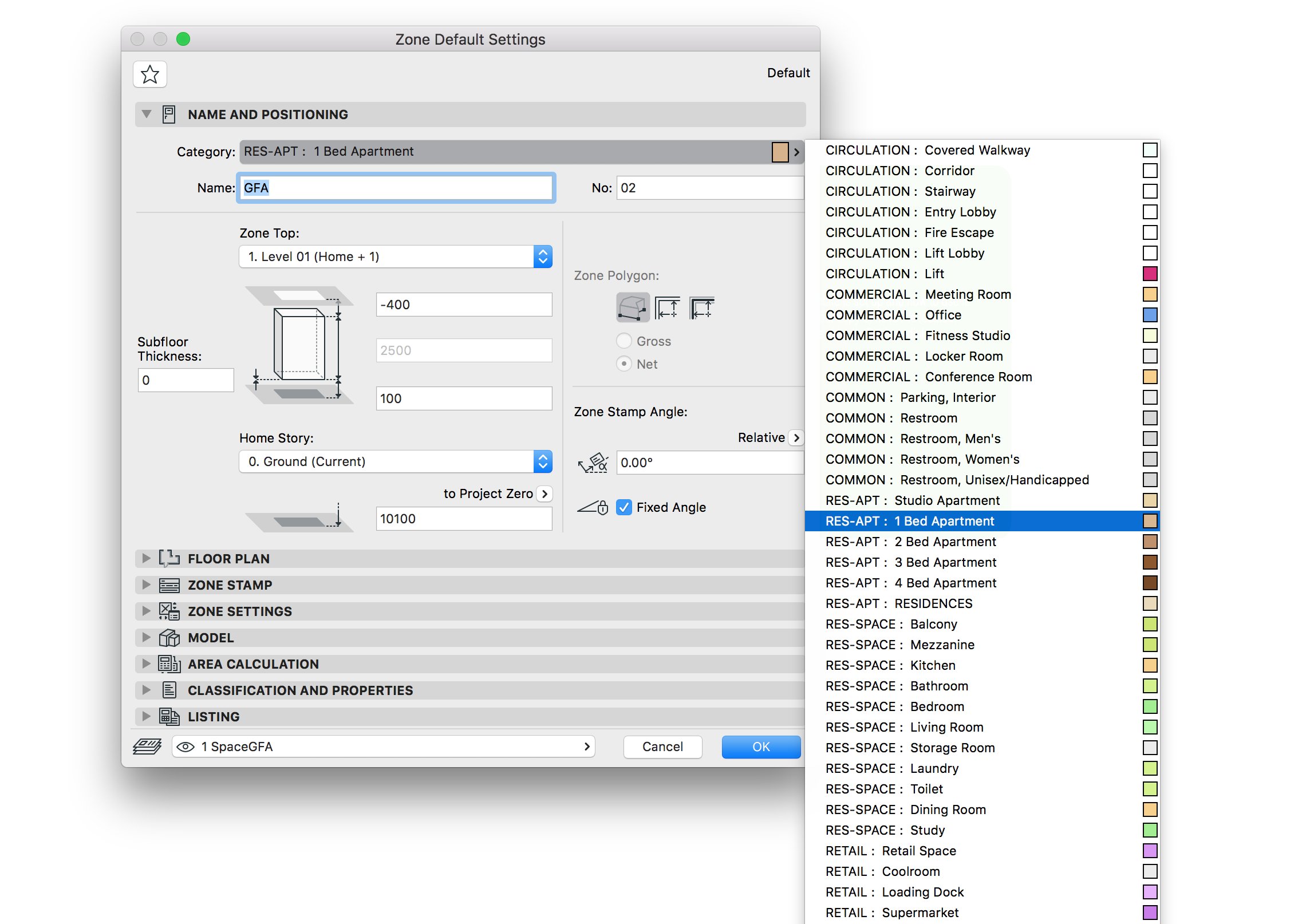
Zones
mACT contains a set of generic Zone categories based on the OmniClass classification system. These Zone categories cover a wide range of building types – generally offices delete categories not typically required for their project types, and then duplicate and modify the generic types to provide specific space-types for their project.
For example residential design practices may make duplicates of the category ‘13-651900 Bedroom’ to develop sub-categories such as Master Bedroom, Guest Room, Nursery, etc
[asideguide type=”tip”]The Extras folder included in your copy of mACT contains the sub-folder Documentation>Omniclass, where you can find pdf’s of the omniclass categories. Alternatively you can download the latest from this website.[/asideguide]
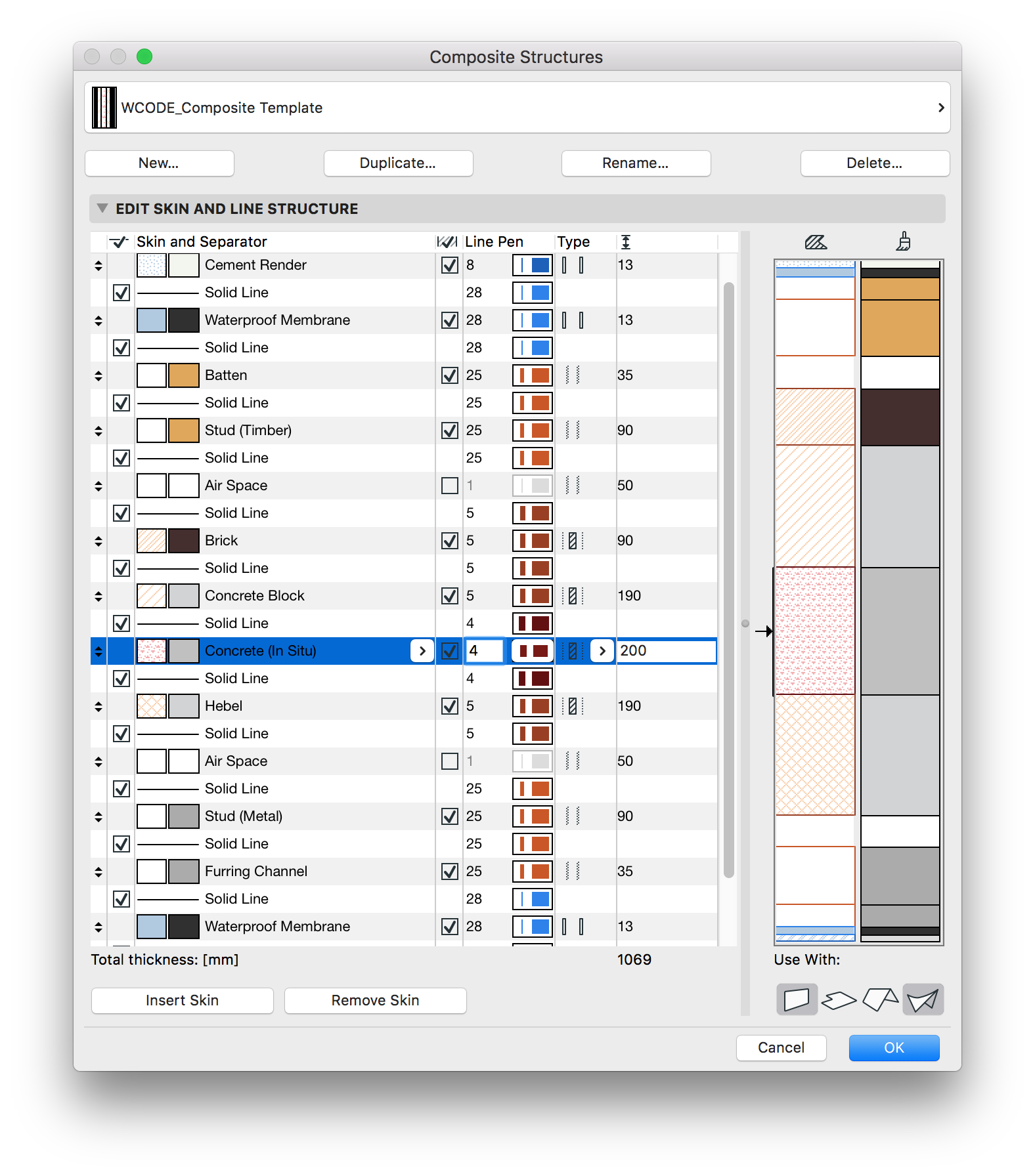
Composites
Unlike the other Attributes, mACT contains only a few predefined Composites. Our experience has shown that the types of composites required for various Wall, Floor and Roof structures are very specific to particular project types, designers and builders preferences. In addition they are different between most projects and require an experienced user / Architect to set them up, as often they are the primary cause for later legal disputes. The mACT approach to Composites is to provide template composites which provide a starting point from which users can develop the composites typically used on their projects.
The primary composite provided is the ‘Composite Template’ (shown below) which contains layers of commonly used building materials or systems with the correct Intersection Priorities, Pens, Linetypes and Fills assigned. An experienced Architect should duplicate this composite and then delete / modify the skins as required to form the composite system desired.
We have also provided a few simple composites which illustrate setup for external and internal walls.
Complex Profiles
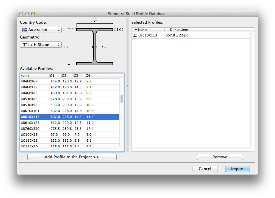
mACT provides a single example steel profile however an extensive list of standard steel sections can be added to the projects Complex Profiles database as required via the menu item Options > Import Standard Steel Profile.
The only modification required by a user to these imported steel profiles is to assign the correct Pens and Intersection priorities. Typically these imported profiles are Steel, thus the single Profile provided with mACT can be used as a template for these properties (Opt-Click the existing profile to grab attributes, then Cmd/Ctrl-Opt-Click on the target to inject properties).
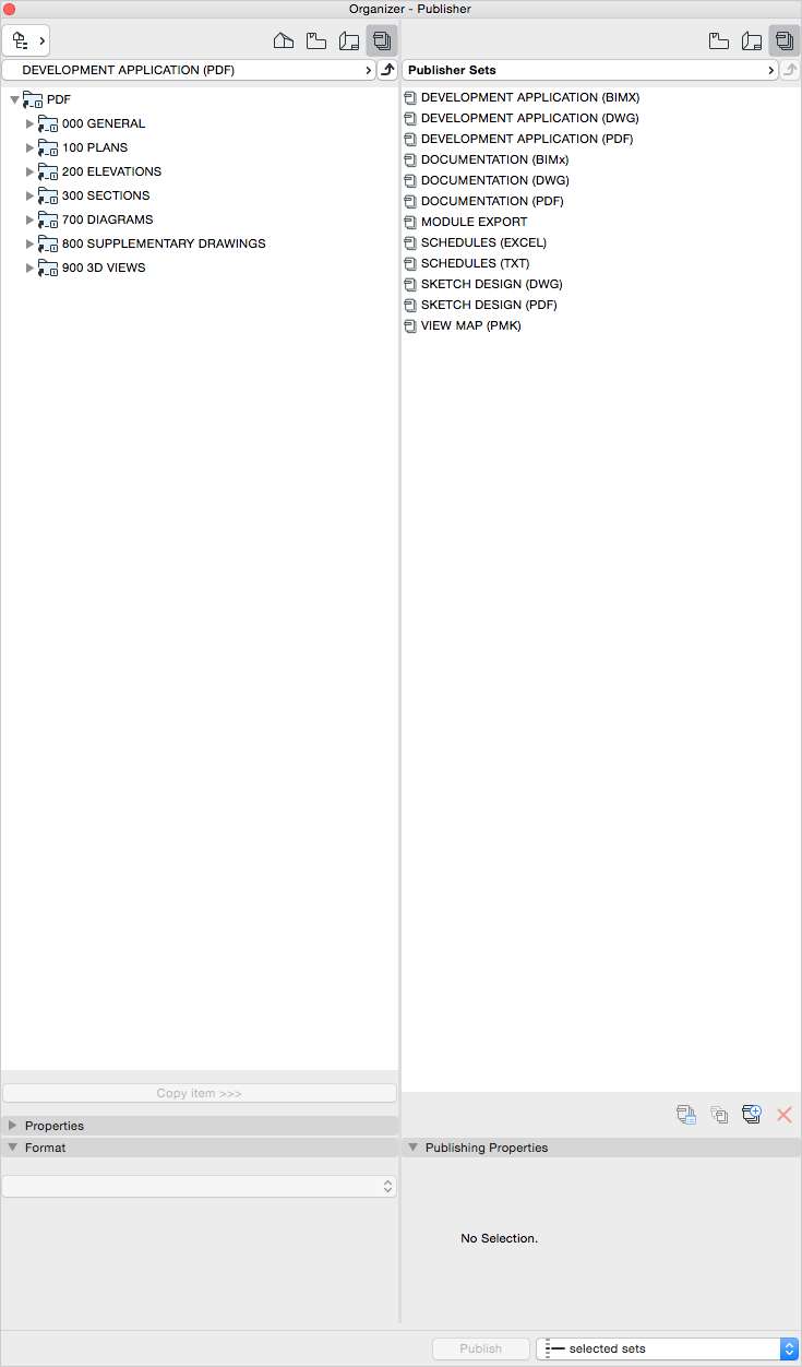
mACT : Organizer
From Project Map to View Map to Layout Book to Publisher Sets, mACT comes pre-configured with a number of Saved Views, Drawing packages in the Layout Book as well as Publisher Sets accounting for the typical required output.


Drawing Numbering System
The mACT Drawing Numbering System is based on the United States National CAD Standard (USNCS), which within the provisions of the standard has been adjusted to suit the specific requirements of Australian projects. This system allows for a great flexibility in organising your drawing package, whether for a large or small project.
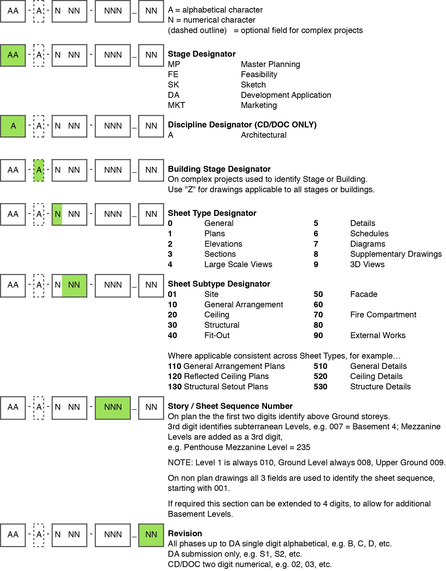
Note that mACT’s layout book has been pre-configured to use this numbering system.
[asideguide type=”alert”]To avoid accidental drawing re-numbering, the numbering is managed manually rather than automated by ARCHICAD.[/asideguide]
Drawing Titleblocks
The mACT Titleblock system consists of two components.
The first is that the bulk of the titleblock is drawn on a Master Layout using Text, Lines and Fills (and images for logos if required). Text can either be static or Autotext (example of the latter is the Layout Title).
The second are the Revision notes and Northpoint which are placed on each Layout individually (NOT the Master Layout). The Northpoint object can be found in the mACT Library.
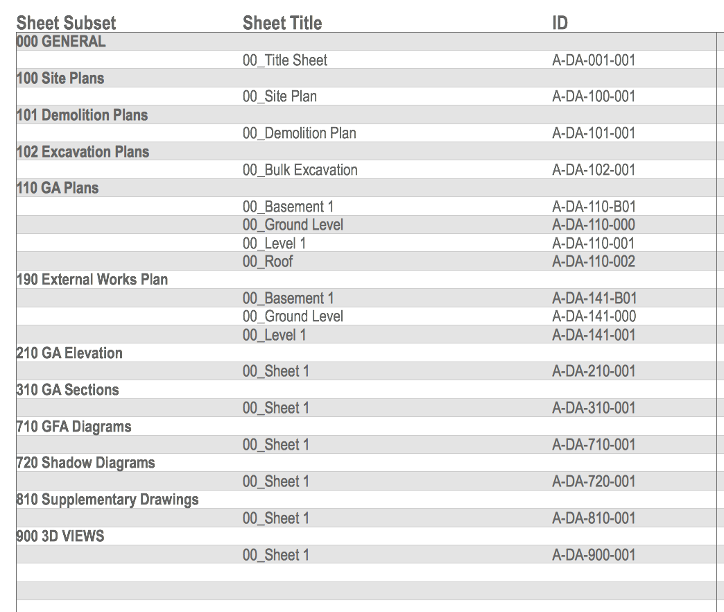
Layout specific information, such as revision letter / number, can be found in the individual Layout’s settings. mACT also includes a Drawing List under Schedules, which gives you an overview of all Layouts in a given set. You can edit the Layout settings directly in this schedule.
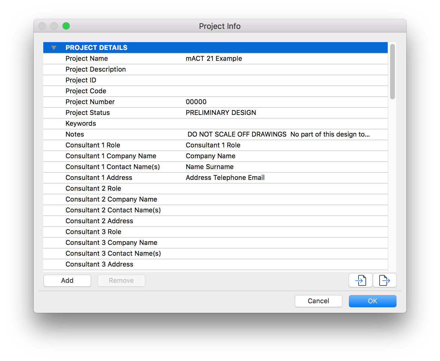
Project Info
mACT makes extensive use of the Project Info to display information on the Titleblock via Autotext.
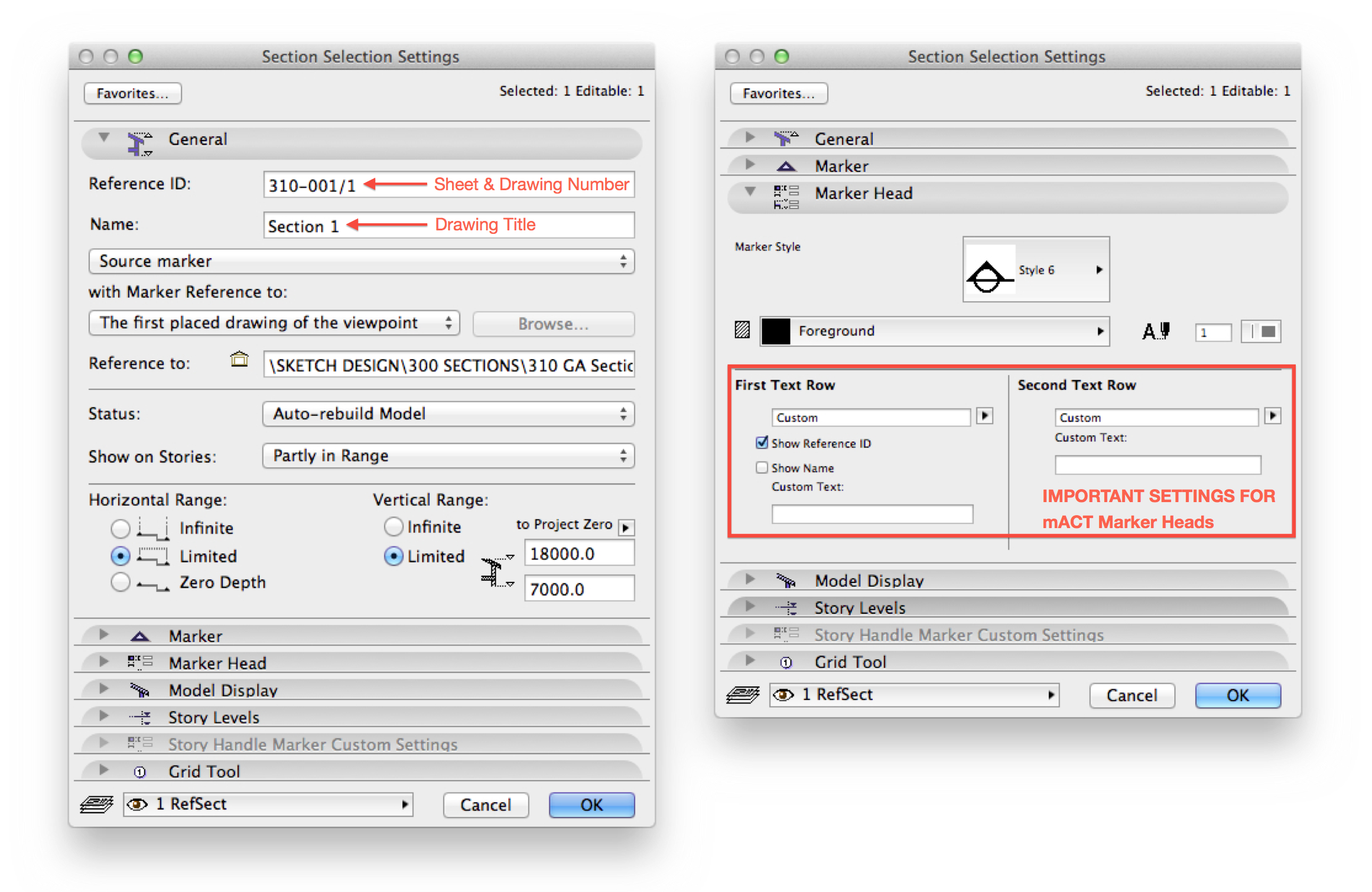
Drawing Marker Referencing
Due to the inclusion of a Layout Revision into the Layout ID field (e.g 123-456_01) mACT requires the use of customised Drawing Markers for Sections, Elevations, Details and Worksheet Markers. These can be found in the mACT Library – please refer to images below for the required settings.
Note that the Layout Number and Drawing ID input into the Drawing Marker need to be manually coordinated with the actual Layout Number and Drawing ID of the drawing placed on the layout – they are not automatically linked.
We note this does not make use of ARCHICAD’s ‘automated’ cross referencing, however in our experience once drawings are issued, sheet numbers do not change however sheet revisions do change – which is where the advantage of using a field in the Layout ID for Revision lies.
Graphic Output Control
Graphic output in ArchiCAD is managed in several places: Model View Option, Graphic Overrides & Renovation Filter. (And as discussed earlier Pen Set, Layer Combination & Scale.)
Model View Options (MVO)
mACT includes MVO to suit a variety of desired outputs:
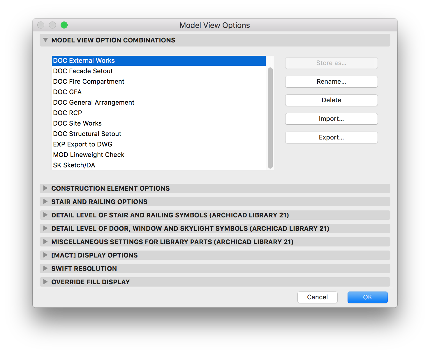
Sub settings allow for control of mACT & Cadswift library parts.
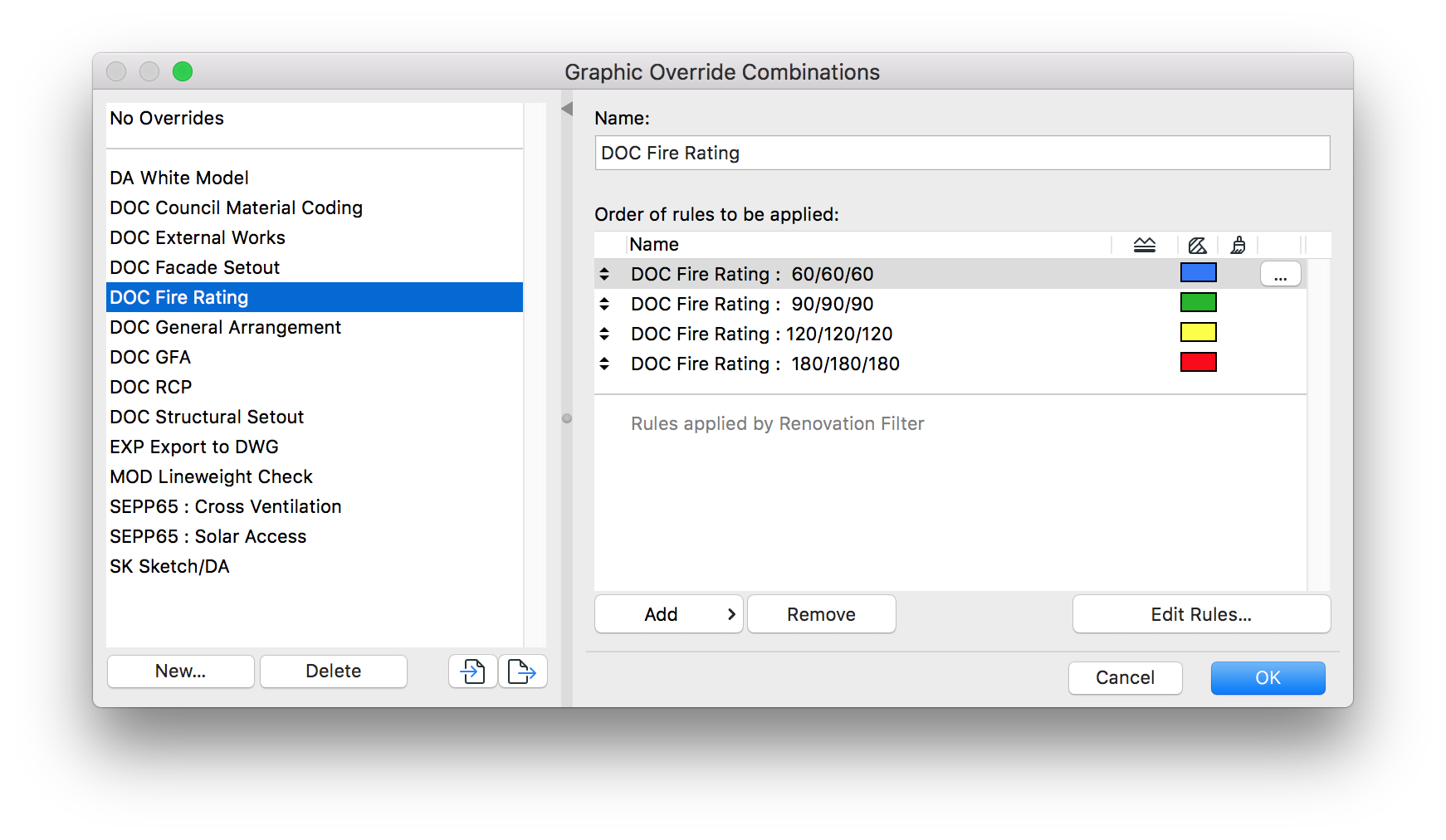
Graphic Overrides
Since ArchiCAD 20 Graphic Overrides are available.
mACT includes overrides to display Fire Resistance Levels of Walls by colour using the listing & properties set in individual elements as well as DA Council Coding of materials by colour.
mACT : Revision System
As an alternative to the inbuilt ARCHICAD Revision Manager, mACT offers a revision system that is straightforward and simple.
Revision letters / numbers are part of the Layout’s settings Autotext fields.
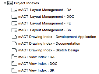
You can review and edit layout revision and name directly in the mACT Transmittal Index relevant to the project phase located in Project Map > Project Indexes.
Transmittal Setup
mACT includes a semi automated setup for transmittals.
It uses a (static) Worksheet together with a schedule that lists layouts dedicated to keeping track of drawing issues.
This transmittal needs to be set up before the first time drawings need to be issued. This involves a few steps:
- Open the mACT Transmittal Index relevant to the project phase located in Project Map > Project Indexes.
This should list all layouts that are part of your layout book (relevant to the project phase).
Go Edit > Copy (COMMAND +C does not work!). - Open the worksheet called A-000-000 Drawing Transmittal.
- Paste the copied info from the schedule into the correct location.
No further formatting should be needed to make the text fit in the worksheet’s drawn table.
Note that the copy / pasted info is no longer linked to the mACT Transmittal Index!
While in suspended group mode, delete the column titles from the pasted info as they overlap with the ones already present on the worksheet.

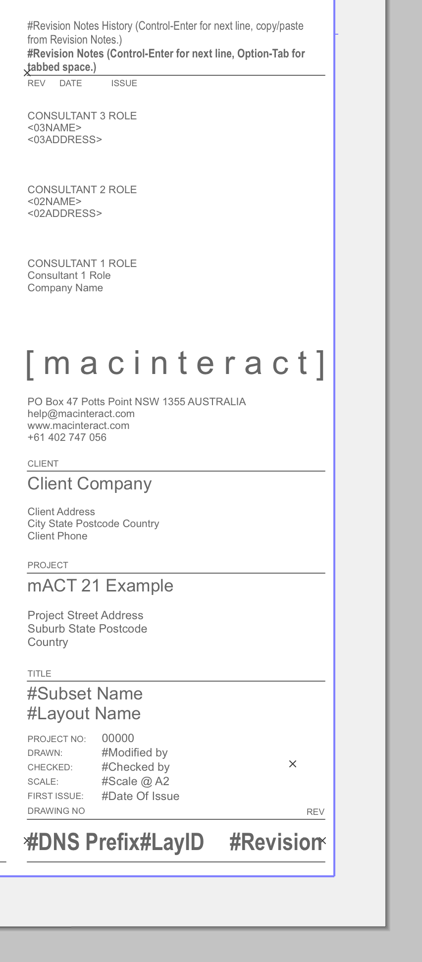
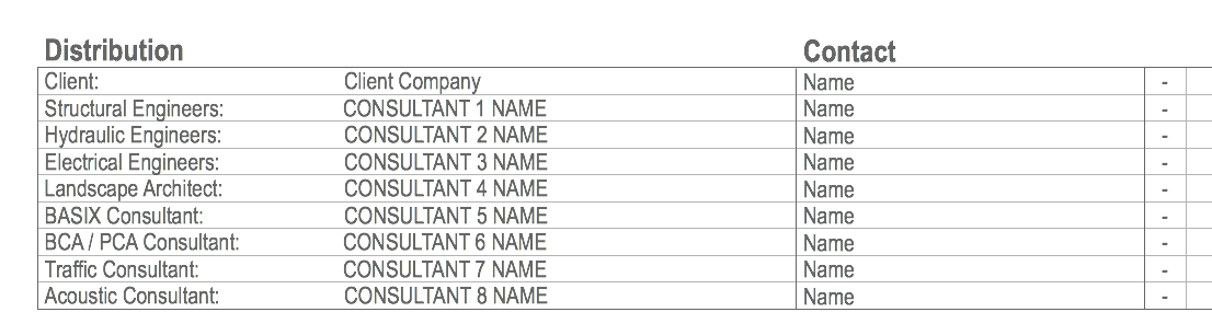
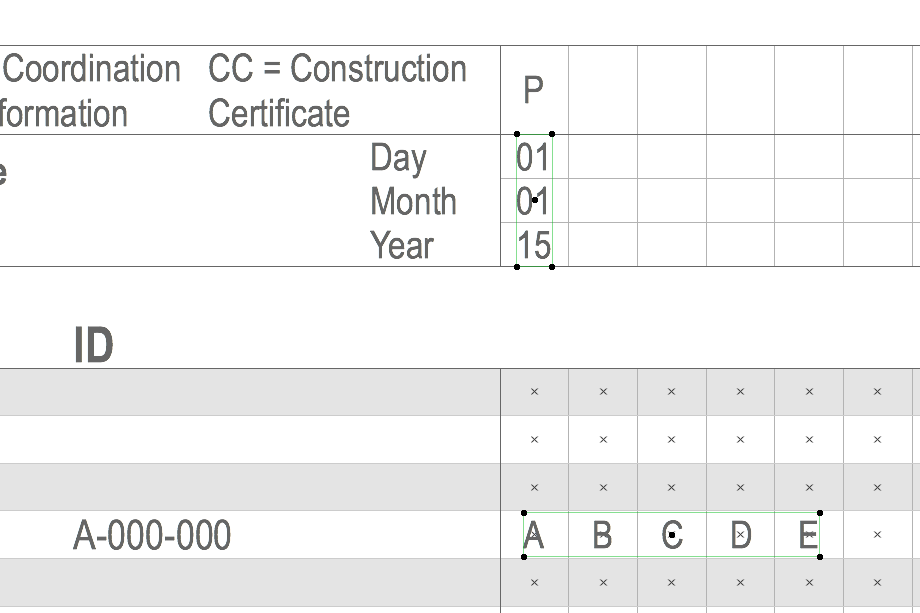
- Set up Consultant information in the ARCHICAD > Project Preferences > Project Info’s Consultants section. Note that this part of the transmittal uses a combination of Auto-Text (In capitals in the image below) and regular Text! You most likely have to adjust this part of the transmittal to meet your specific requirements.
A note on Auto-Text.
Set up and use Auto-Text when it concerns information that is used frequently and in various locations. For example, the consultant company & address may appear on various master layouts, whereas the contact name of the individual is only relevant on the transmittal, therefore the latter should be regular text.
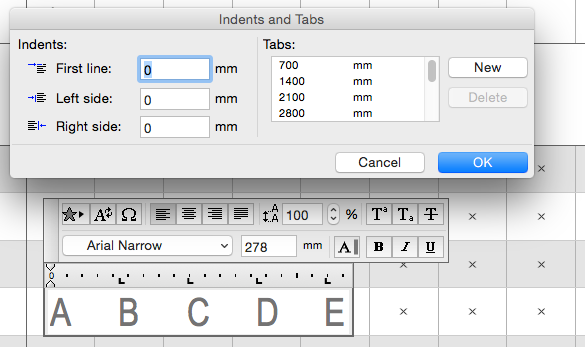
- Add the revision information.
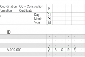
Note that the text has been formatted to fit, i.e. you can double click the revision text (see image below) and use the TAB key to jump to the next position. (Right Click the ruler to access the Indents and Tabs settings.)

[asideguide type=”tip”]You can open the mACT Transmittal Index on the side as a reference as it will list all layouts with their names and revision code prefix.[/asideguide]
- If layouts are added and subsequently need to be inserted in the drawing schedule then this is best done manually as opposed to repeating step 1-2-3. Otherwise you won’t be able to tell which previous issues belong to which layout.
- The Saved View of the A-000-000 Drawing Transmittal worksheet is placed on two layouts:
- Static sections are placed on the Master Layout, preventing them from being edited.
- Sections subject to change are placed on the Drawing Transmittal Layout (located at the top of your Layout tree). This allows you to move the drawing content over, if, god forbid, you have more revisions than currently fit on the layout.
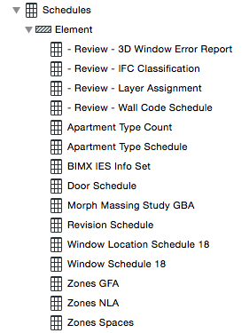
Schedules & Indexes
mACT includes several pre-configured Schedules & Project Indexes to help you schedule areas, windows / doors, Views as well as review drawn elements:
Additional resources
Tips and Tricks > macinteract.com/blog
Feedback > please email us
ARCHICAD Training > macinteract.com/training
ARCHICAD User Forum > archicad-talk.graphisoft.com
CADSWIFT Library parts > cadswift.com.au
Natspec
Worksection Classification List
National Worksection Matrix (PDF)
OmniClass